Dalian Marine Diesel Engine Co., Ltd. Gao Bo
With the rapid development of manufacturing technologies and the growing demand in the market, the operating speed of low-speed diesel engines is gradually approaching the most efficient propulsion speed of the propeller. As a result, engine design is moving toward lower speeds, lighter weight, and more compact structures. To achieve this, the stroke-to-bore ratio of these engines has been continuously increased. For instance, the newly developed G model by Mann and the X model by Wärtsilä have a stroke-to-bore ratio of 4.65 and can operate as low as 66 rpm. This shift presents significant challenges, especially in the machining of large structural components, where the frame’s processing is particularly sensitive to changes in the stroke length.
### 1. Challenges in Rack Machining
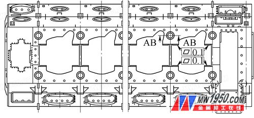
(1) The rack is a massive box-type component, with dimensions ranging from 15 to 22 meters in length, 5.65 meters in width, and 5 meters in height. The large holes and openings make it difficult to handle, and the workpiece tends to deform significantly during flipping (see Figure 1).

Figure 1: Top View of the Rack
(2) The entire frame is constructed using multiple welded steel plates, resulting in a complex weld bead pattern. These welds create high internal stresses, which can lead to deformation after machining if not properly managed.
(3) The precision requirements for the guide slide of the frame are extremely high, making it one of the biggest challenges in the machining process. With the increased stroke of the main engine, the frame becomes taller and the guide plate longer. This increases the risk of reduced rigidity and machining vibrations due to the overhang of the machine ram.
(4) The large openings at the bottom ends of the frame reduce its rigidity, making it prone to chatter and tool chipping during machining. This results in poor surface finish and excessive tool wear.
### 2. Process Solutions for Rack Machining Challenges
To address these difficulties, the following strategies can be implemented:
(1) Due to the potential deformation during the turning process, the most critical surfaces—such as the guide slides—must be machined after the final station and then flipped 180 degrees to ensure accuracy and stability.
(2) If possible, the rack should undergo stress-relief annealing in a heat treatment furnace after welding. In cases where heat treatment is not available, the workpiece should be rough-machined and left to age for a period to allow internal stresses to dissipate before final machining.
(3) For machining the guide rails of the frame, the CNC gantry milling machine must meet specific requirements. First, the table's length and width should be sufficient, with a minimum width of 6 meters. Second, when the machine beam is raised, the height to the work surface should be at least 7 meters (greater than the pad height plus the workpiece height plus the milling head length). Third, the machine ram's travel should ideally reach 3.5 meters, ensuring that the combined stroke of the ram and the milling head exceeds the machining height of the guide rail by at least 5 meters (see Figure 2).
These measures help maintain precision and stability throughout the machining process, even with the increased complexity brought about by modern engine designs.
For more detailed information, please download the attachment or refer to *Metalworking (Cold Processing)*, Issue 23, 2013.
Shower Head
Shower Head,Round Rainfall Shower Head,High Pressure Rainfall Shower Head,Low Flow Shower Head,Top Spray,overhead shower
Kaiping Rainparty Sanitary Ware Technology Co.,Ltd. , https://www.rpshower.com

