Our company's L series and D series diesel engine timing gear chambers and gear chamber covers are thin-walled iron castings or cast aluminum parts with complex shapes. There are dozens of varieties, most of which are manufactured by professional manufacturers. The annual output of the two types of parts is about 200,000 pieces each. During the plane processing of the gear chamber and the gear chamber cover, the main problem is that the flatness is out of tolerance or unstable, which affects the positional accuracy of other machining holes on the parts, and causes the gear chamber and the gear chamber cover to be assembled at the joint surface of the parts. Oil leakage. Taking the KM496BT gear chamber and 4L22TDI gear chamber cover plane processing of our company as an example, the influencing factors of flatness tolerance in the processing process are analyzed and the solutions are proposed.
   Gear room and gear chamber cover structure
Figure 1 and Figure 2 show the KM496BT gear chamber, 4L22TDI gear chamber cover structure and plane accuracy requirements.
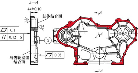
Figure 1 Schematic diagram of the KM496BT gear chamber structure and plane accuracy requirements
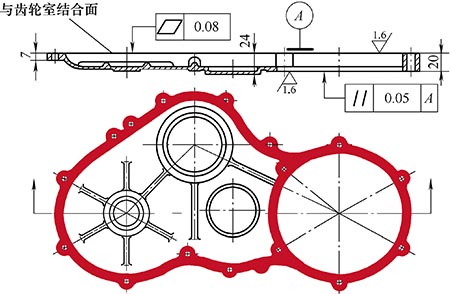
Figure 2 Schematic diagram of 4L22TDI gear chamber cover structure and plane accuracy requirements
The KM496BT gear chamber is a cast iron material part with a multi-step composite structure with a wall thickness of 5 mm. The length is 496 mm and the width is 288 mm. The thickness of the joint surface of the cylinder joint surface and the gear chamber cover is (44 ± 0.10) mm. The flatness requirements of the joint surface of the cylinder joint surface and the gear chamber cover are 0.08 mm and 0.10 mm, respectively.
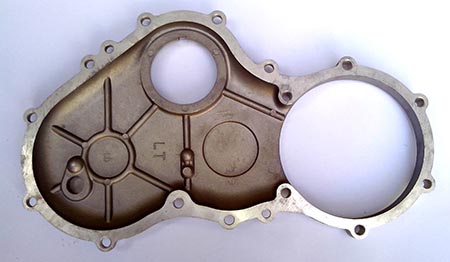
The 4L22TDI gear chamber cover is made of cast aluminum material and has a thin-walled shell structure with a wall thickness of 5 mm. The length is 398mm and the width is 230mm. The minimum thickness of the machined surface is 7mm and the maximum thickness is 20mm. The flatness of the joint surface with the gear chamber is required to be 0.08 mm.
The common feature of the KM496BT gear chamber and the 4L22TDI gear chamber cover is the thin-walled parts with complex structure and poor rigidity.
According to the preliminary analysis, during the processing of the gear chamber and the gear chamber cover, the flatness is mainly caused by the unreasonable arrangement of the workpiece processing, the internal stress of the workpiece casting blank, the uneven hardness of the workpiece working surface, the workpiece positioning and clamping deformation, and the workpiece cutting. Caused by deformation and improper placement of the workpiece. The following analysis and propose solutions.
   2. Unreasonable processing arrangement causes flatness
At present, the plane processing of the gear chamber and the gear chamber cover generally has the following process arrangements.
(1) Milling the machining plane with a milling machine. The process arrangement is: rough milling → semi-finishing milling → finishing milling. With this type of processing, the flatness of the machining surface of the gear chamber and the gear chamber cover is generally 0.08 to 0.12 mm. The disadvantage is that the flatness fluctuates slightly, and the advantage is high processing efficiency.
(2) The plane is machined by a combination of a milling machine and a surface grinder. The process arrangement is: rough milling → semi-finishing milling → fine grinding. With this type of processing, the flatness of the machining surface of the gear chamber and the gear chamber cover is generally 0.08 to 0.10 mm. Compared with all the milling operations of the plane, the milling and grinding combined processing method is relatively inefficient, but this processing method is used more in production because it can better meet the flatness requirements of the machined surface of the part.
Another process arrangement for machining planes using a combination of a milling machine and a surface grinder is: rough milling → rough grinding → fine grinding. Compared with the previous processing method, the processing accuracy of the plane is basically the same. Compared with milling fixtures, the grinder fixture structure is relatively simple and the investment cost is relatively low, but the plane grinding efficiency is lower than the milling efficiency.
(3) For some gear chambers or gear chamber covers with complex structural shapes that cannot be positioned and clamped, the workpiece can be directly processed by the workpiece adaptive grinding method. That is, the workpiece processing surface is the positioning surface, and the workpiece processing surface is pressed against the grinding wheel by the workpiece's own mass or external elastic force, and the workpiece processing surface is adaptively positioned and ground. This type of processing is suitable for gear housings or gear chamber covers with high precision casting and small machining allowance. The grinding precision and machining efficiency are high, but special grinding equipment is required, which requires high precision of grinding wheel and grinding wheel strength. .
The above three processing methods are used in actual production. How to choose specifically depends on the accuracy of the workpiece plane machining accuracy and the specific process equipment of the production unit. If the process is improperly arranged, the flatness of the gear chamber and the gear chamber cover is not easy to guarantee.
For example, some production units directly arrange the fine grinding after the rough milling gear chamber and the gear chamber cover plane. Although this kind of processing method simplifies the process flow, due to the large processing error of rough milling plane, the rough machining error is not released and corrected in the middle. The problems caused by direct fine grinding are: 1 To eliminate the machining error caused by rough machining, it is necessary Increase the grinding allowance and reduce the processing efficiency. 2 When the large amount of grinding is used, the grinding force and the grinding wheel are expensive, and the machining accuracy of the workpiece plane is not easy to guarantee or unstable.
   3. The internal stress of the workpiece casting blank causes the flatness to be out of tolerance.
After the gear chamber and the gear chamber cover blank are cast, there is internal stress, and the workpiece is easily deformed after machining. Especially the thin-walled parts such as the gear chamber and the gear chamber cover are obviously deformed after processing. If some of the workpieces have just been processed, the measurement flatness meets the requirements, but after a period of time, the workpiece is deformed and the flatness is out of tolerance.
After casting the gear chamber and the gear chamber cover blank, in addition to properly extending the sand box insulation time, the blank should be subjected to stress relief annealing or other aging treatment to ensure that the internal stress of the workpiece casting blank meets the design requirements of the product pattern.
   4. The unevenness of the hardness of the workpiece working surface causes the flatness to be out of tolerance.
If the hardness of the machining surface of the gear chamber and the gear chamber cover blank is not uniform, in the milling process, the portion with high hardness is resistant to the knife, and the portion with low hardness is dug deep, and the flatness of the workpiece is not easily guaranteed.
After the gear chamber and the gear chamber cover blank are cast, the cooling speed of different parts is guaranteed to be the same. For the fast cooling part, measures to reduce the cooling rate are adopted. At the same time, the proportioning composition of the blank material and the pouring temperature of the molten iron are strictly controlled to ensure that the hardness difference of the casting on the same processing surface is not more than 20 HBW.
   5. Workpiece positioning and clamping deformation cause flatness deviation
During the processing of the gear chamber and the gear chamber cover surface, due to the unreasonable selection of the workpiece positioning and clamping position, the workpiece is subjected to stress deformation, which is the main cause of the flatness. This requires that in the design of the fixture, the position of the workpiece and the position of the clamping point should be reasonably arranged according to the structural rigidity of the workpiece and the deformation characteristics, and the deformation of the workpiece caused by the positioning and clamping factors should be minimized. The fixture design should focus on the following aspects:
(1) The position selection of the workpiece fixed positioning point and floating support point should be reasonable. When arranging the machining positioning points, the parts with large bearing range, stable workpiece placement and good rigidity should be selected as the three fixed positioning points. At the same time, it should also consider whether the position of the selected fixed positioning point is suitable for arranging the clamping platen, whether it is convenient for loading and unloading the workpiece, whether it can improve the rigidity and cutting stability of the workpiece.
The three fixed positioning points are selected on the same height surface of the workpiece as much as possible to ensure the height of the positioning points. If three fixed positioning points are selected on different height positioning surfaces of the workpiece, there are casting height errors or machining height errors between different height positioning surfaces. When the workpiece is positioned, the positioning surface of three different heights on the workpiece and three different heights The fixed positioning points cannot be effectively contacted at the same time, and after the workpiece is clamped, it is easy to produce unequal positioning deformation. In particular, when the area of ​​the positioning point is relatively large, the deformation of the workpiece caused by the positioning of the workpiece with the unequal positioning surface is larger.
After the position of the fixed positioning point of the workpiece is selected, in order to improve the support rigidity and machining stability of the workpiece, according to the structural shape of the workpiece, a floating support is added to the weak portion or the poor rigidity of the workpiece to prevent clamping deformation and cutting deformation. Or a phenomenon such as chipping during cutting. The support height of the floating support and the support force should be set appropriately. It is necessary to ensure reliable support for the workpiece, and to ensure that the original positioning of the workpiece is not damaged and no support deformation occurs. The floating bearing should be reliably locked in the working state, and should not be loose or floating during the cutting process, which affects the normal processing of the workpiece.
(2) The clamping position selection should be reasonable. After the position of the fixed positioning point and the floating supporting point of the workpiece is determined, the position of the clamping point is selected to coincide with the fixed positioning point as much as possible without affecting the loading and unloading of the workpiece and the cutting of the tool. Even if the clamping point does not coincide with the fixed positioning point, the clamping point should be placed around the fixed positioning point or on the auxiliary support. If affected by the structure of the workpiece or other factors, the clamping points cannot be arranged in the above parts. In the worst case, the clamping points should be placed in the part with good rigidity and small clamping deformation to minimize the clamping deformation of the workpiece. When selecting the position of the clamping point, it should also be considered to ensure that the workpiece is clamped reliably and does not damage the original positioning of the workpiece.
(3) Selection of manual fixtures and automatic fixtures. In the processing of gear chamber and gear chamber cover, manual positioning clamping fixture or automatic positioning clamping fixture is adopted, which is mainly determined according to the production batch size of the workpiece and the actual situation of the production unit. In our company's gear room and gear chamber cover, there are more manual positioning clamps and semi-automatic positioning clamps. The workpiece is machined by manual or semi-automatic fixtures, and the machining accuracy of the workpiece plane is greatly affected by the operator's operating skills.
Figure 3 shows the 4L22TDI gear chamber cover milling combined surface fixture structure. The fixture is mounted on a vertical milling machine to machine the workpiece and is manually positioned and clamped. The workpiece is positioned by three contour cylinder positioning points on the same plane (three red cylindrical points in the figure). Five floating support points are arranged around the middle and the middle of the workpiece to increase the support rigidity of the workpiece. The main pressure plate is pressed against the floating support point at the intermediate portion. Four horizontal sides are tightened at the corresponding parts of the workpiece to improve the clamping stability of the workpiece and prevent vibration during the machining of the workpiece. The workpiece loading and unloading operation steps are: placing the workpiece processing joint face up on the fixture positioning point, pressing all the floating support points by the workpiece own mass→locking the intermediate floating support corresponding to the main pressure plate→putting the main pressure plate to press the workpiece→ Lock the surrounding floating support → Tighten the horizontal side tightly → After the workpiece is finished, loosen the horizontal side clamping → Remove the main pressure plate → Remove the workpiece → Loosen all the floating bearings → Reload the workpiece. The workpiece loading and unloading time of this fixture is about 1min, and the flatness of the workpiece processing surface is ≤0.08mm, which satisfies the machining precision requirements and production tact requirements of the workpiece.
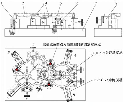
Figure 3 4L22TDI gear chamber cover milling combined surface fixture structure
1. Three positioning horns 2. Gear housing cover 3. Five floating supports 4. Main pressure plate 5. Opening washer 6. Clamping rod   7. Fixture bottom plate 8. Four sides are tight
   6. The cutting deformation of the workpiece causes the flatness to be out of tolerance
Plane milling cutters generally have four types of lead angles: 45°, 60°, 75°, and 90°. Which type of main-angled face milling cutter is used should be determined according to the material and structural characteristics of the machined parts, the performance of the machine tool, and the rough and fine machining. Milling thin-walled parts with poor rigidity and easy deformation, generally choose the face milling cutter with 90° lead angle, which has less influence on cutting deformation. At other angles, the main-angle face milling cutter has a cutting force that is pressed into the workpiece during the cutting process, which is easy to cause elastic or plastic deformation of the workpiece, so that the flatness of the workpiece after milling is not easy to guarantee.
Figure 4 shows the cutting force distribution on the base of a 45° main angle face milling cutter. Fx is the cutting component of the cutting edge feed direction, and Fy is the cutting component of the cutting edge cutting depth. On the base surface of the tool, Fy is perpendicular to the direction of the tool feed motion, which is a component force that is pressed into the workpiece, which is easy to cause cutting deformation and cutting vibration of the workpiece, resulting in plane machining error.
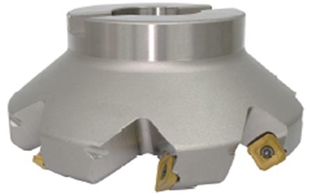
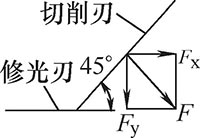
Fig. 4 Distribution of cutting force on the base surface of 45° main angle milling cutter
Figure 5 shows the cutting force distribution on the base of a 90° main angle face milling cutter. During the cutting process of the tool, only the cutting component force Fx in the feeding direction is obtained on the cutting edge, and the plane machining error caused by the cutting force is small.
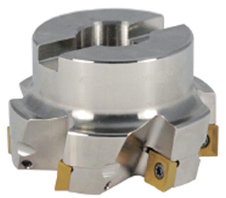
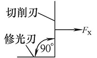
Fig.5 Distribution of cutting force on the base surface of 90° main angle cutter
Milling the gear chamber, gear chamber cover and other thin-walled parts with high flatness requirements, and also ensure that the milling machine spindle is perpendicular to the work surface. Before machining, check the end face of the milling machine spindle to jump <0.02mm.
   7. Improper placement of the workpiece results in flatness
If the workpiece is placed improperly between the gear chamber and the gear chamber cover processing or after the machining is completed, the workpiece may be deformed and bumped, resulting in poor flatness.
Figure 6 shows the stacking of gear chambers between processes. The workpiece is prone to deformation and bumping, and workpiece turnover between processes is not convenient. Figure 7 shows that the inter-process and finished gear chambers are placed vertically in a dedicated station tool, which can effectively prevent deformation and bumping of the workpiece, and facilitate workpiece turnover.
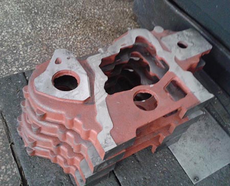
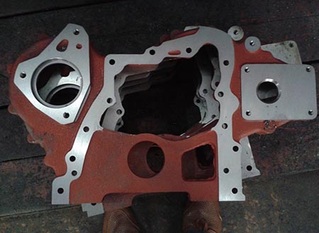
Figure 6 Stacking of gear chambers between processes
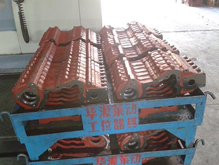
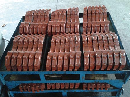
Figure 7: The process and the finished gear room are placed vertically in the station
   8. Conclusion
Through the analysis of the factors affecting the flatness deviation of the KM496BT gear chamber and the 4L22TDI gear chamber cover surface, the solution to improve the flatness of the thin-walled part surface is proposed from several aspects, which is similar to the gear chamber and the gear chamber cover. The improvement of the surface processing quality of the parts provides a reference.
   references:
[1] Chen Xinzhao. Mechanical Processing Equipment Design Manual [M]. Beijing: Mechanical Industry Press, 1998.
Mate Tea Strainer Straw,Stainless Steel Mate Tea Straw,Resable Drinking Mate Tea Straw,Colorful Mate Tea Straw
YANGJIANG VOSSEN INDUSTRY AND TRADE CO.,LTD , https://www.cnvossen.com